
 The RF Planning tool gives the user the ability to make RF predictions based on the 3D terrain data. RF Plans are collections of RF Transmitters. Each RF Transmitter can be individually configured, with many parameters able to be modified.
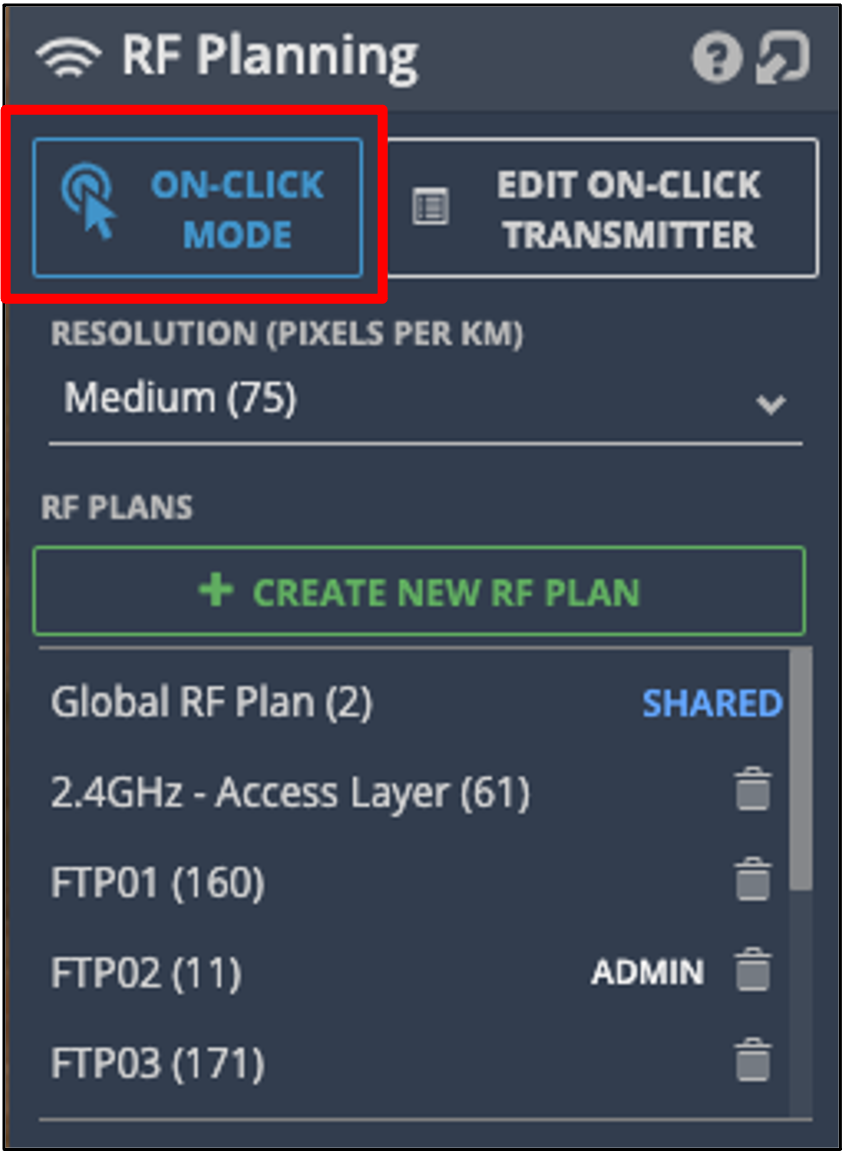
There is a simple way to use RF Planning, it is called On-click Mode. This mode allows a user to point and click to see what the expected coverage pattern from a single transmitter would look like on the ground.
The Resolution setting gives the flexibility of creating RF plans over a wider area, with the trade – off, of the plan being of a lower resolution.
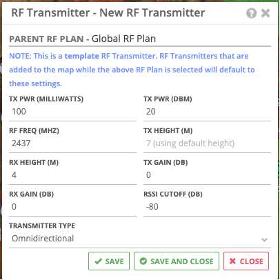
You can set up the on-click defaults by editing the information in the Edit On-click Transmitter section:
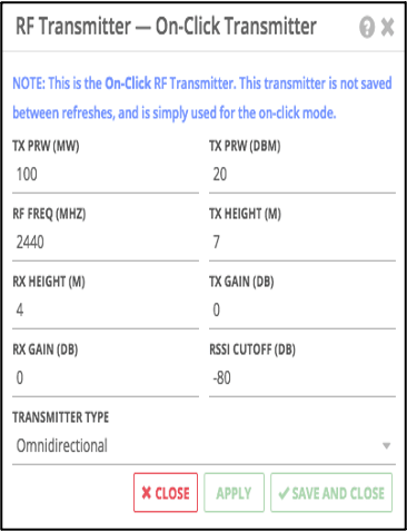
TX Power (mW) – The Tx Power in milliwatts of the RF Transmitter (not editable if a radio is selected)
TX Power (dBm) - The Tx Power in dBm of the RF Transmitter (not editable if a radio is selected).
RF Freq (Mhz) - The RF Frequency of the RF Transmitter.
Tx Height (Meters) - The transmitter height in meters.
Rx Height (Meters) - The receiver height in meters.
Tx Gain (dB) - The transmitter total gain in dB.
Rx Gain (dB) - The receiver total gain in dB.
RSSI Cutoff (dB) - RSSI levels lower than this cutoff will not be rendered.
Transmitter Type - This has three options:
- Omnidirectional (perfect omnidirectional RF Pattern, for simple line of sight/RSSI observation).
- Beam (horizontally and vertically adjustable perfect beam).
- ANT File This option is only available outside of On-Click planning mode.
If you select Beam or ANT File, then there are more options to configure:
- Horizontal Angle (0° to 360°) - [Beam & Ant File only] The horizontal direction angle in degrees
- Vertical Angle (-90° to 90°) - [Beam & Ant File only] The down tilt angle in degrees (negative points further up, positive points further down)
- Beam Width (0° to 360°) - [Beam Only] The beam width angle in degrees
- Beam Height (0° to 180°) - [Beam Only] The beam height angle in degrees
- Select Ant File - [ANT File Only] This field allows the user to select or upload an ANT v3 File for use as the RF Propagation pattern
From that point in every click you make in that mode will be using those settings. You can hold down the control key to keep your previous on-click plan/s visible.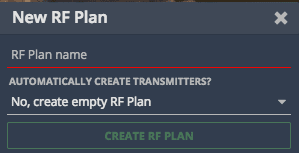 To use the RF Planning functionality to generate site wide plans we want to use the Create New RF Plan button. The user is then asked to give the RF plan a name and whether or not to automatically create transmitters, as the following:
The user should give the plan a Name and then from the "Automatically Create Transmitters?" Drop-down select Create transmitters for each radio. This mode is the simplest form of the advanced mode and allows IMS to pre-fill radio transmitter data from its known information.
You will then have several other options to configure, which are:
Create Transmitters for These Asset Types – here you should type out trailer or tower or both.
With IP Devices of These Types – this is where you select the type radio, your AP or backhaul radio type.
For Radios of This Frequency – finally, for which chipset (band) you would like to do a plan for, 2.4Ghz or 5.8Ghz.
Once you have clicked apply you will see your new RF plan is available to use. Click on it and you will see that there are more options to configure.
There are four different Coverage Layer Types available, these determine the colouring of the generated RF Plans:
- RSSI - This generates a 'stepped' RSSI map with three colour tiers.
- RSSI Gradient - This generates a 'gradient' RSSI map with a smooth transition of RSSI colours.
- Overlaps - This is coloured by frequency/channel and is black where there is an overlap of any RF.
- Same Channel Overlaps - This is coloured by frequency/channel and is black where there is an overlap of RF of the same frequency.
Once you have selected the desired type, click Generate Coverage to see your RF plan:
You can access a legend for the RF plan by clicking the legend icon next to a generated Coverage Layer, it looks like three bars stacked on top of each other next to the X icon. This will show a legend for the colours.

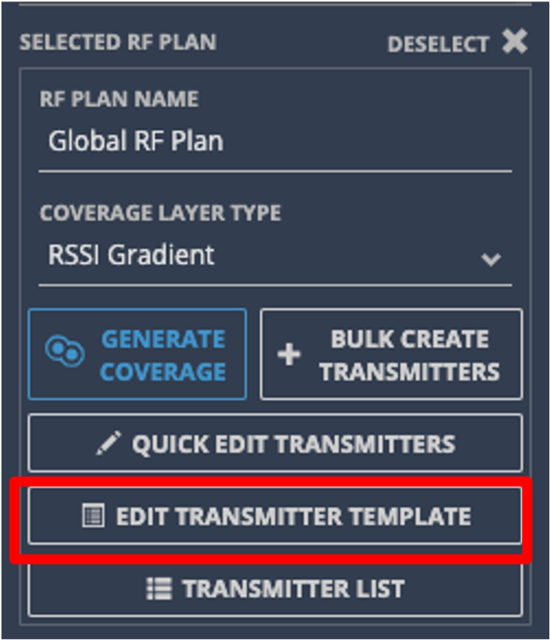
Once an RF Plan has been selected you are able to edit the transmitter template. The options are the same as the On-Click Transmitter editor.
A difference to note is that since RF Plans can assign RF Transmitters to Assets, the height set on the Asset can be used as the height for the RF Transmitter. To use this behaviour make sure the TX height of the transmitter template is cleared.
In this example the RF Transmitter height is set from the RF Transmitter’s parent Asset’s height. In the case the parent Asset does not have a height, the RF Transmitter will use the height of the parent Asset’s, Asset Type, e.g., trailer, tower.
You are also able to edit the template of an RF Transmitter individually by right clicking it on the map and selecting "Edit RF Transmitter". In the context menu you will also have the options to delete and disable the individual RF Transmitter. Deleting an RF Transmitter removes it from the map and also the RF Plan. While disabling a RF Transmitter keeps the transmitter in the plan and on the map but excludes it from the coverage map generated.
You can also do the above in things when in Quick Edit Transmitters mode:
When in Quick Edit Transmitters mode you can move a transmitter by clicking and dragging it (unless it is linked to an Asset), left-click to edit it, right-click to bring up options to delete or disable it and create a transmitter by left-clicking on the map itself.
If you would like to see a list of all the transmitters you have in the current plan you have selected you can click on the Transmitter List button:

When clicked, a panel pops up displaying a list of all the transmitters. Here you can also disable, edit and delete transmitters individually. You are also able to bulk delete them and export selected transmitters.
Note: When a transmitter is disabled it will appear on the map as grey and if you have disabled transmitter selected it will have the following icon next to its name in the infobox as well as in its edit panel:
Underground
Note that this functionality is not available when viewing an underground site.